A lathe tool diagram shows the parts of a lathe and their functions. The diagram provides a visual representation of the different components that make up a lathe and how they work together to cut and shape metal or wood.
Lathe machines are used to turn and shape workpieces on a single axis, while cutting tools are used to remove material. The diagram of the lathe tool typically includes the headstock, tailstock, bed, carriage, and cutting tool. The headstock contains the spindle that holds the workpiece while the tailstock supports the other end.
The bed is the foundation of the lathe, while the carriage moves along the bed to control the movement of the cutting tool. Lastly, the cutting tool is used to remove material from the workpiece. A detailed understanding of a lathe tool diagram is necessary for the successful operation of the machine. The diagram aids operators in identifying the components, and how they work together to make precise cuts on workpieces.
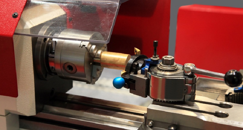
Credit: www.cncmasters.com
The Role Of The Lathe Tool Diagram In Lathe Operations
Table of Contents
Explanation Of How A Lathe Tool Diagram Helps In Understanding The Different Parts Of The Lathe Tool
A lathe tool is an essential component responsible for the precision of lathe operations. It is mainly used for cutting, drilling, or sanding materials uniformly. Understanding the different parts of a lathe tool is essential because it helps the operator to determine the tool’s effectiveness and efficiency.
The lathe tool diagram explains the location and uses of the various parts of the lathe tool. It is essential for beginners and skilled workers who need to identify the tool parts’ location and functioning.
- Handle: This part allows for a good grip and control of the lathe tool. It ensures that the operator has a proper grip without slipping.
- Blade: The lathe’s blade is usually made of high-speed steel, and it determines how smooth or rough the material will be cut.
- Shank: The shank is the part of the tool that attaches it to the lathe’s tool holder.
- Cutting edge angle: The cutting angle of the tool determines the precision of the material while cutting.
- Relief angle: This is the part of the tool that provides clearance, ensuring that the tool does not rub against the workpiece’s surface.
- Nose radius: The nose radius is the curve at the end of the lathe tool. It determines the overall finish of the workpiece’s surface.
Importance Of Identifying Different Lathe Tool Parts To Ensure Proper Functioning
Identifying the various parts of a lathe tool is crucial in ensuring proper functioning. For instance, if the operator doesn’t know the right part, it would be challenging to fix the faults when they arise.
- To avoid causing damage to the tool holder and the lathe’s spindle, it is essential to identify the location and proper installation of the lathe tool.
- Recognizing the relief angle can ensure that the workpiece’s surface is not damaged, and it can effectively remove burrs from the edges of the workpiece.
- Correctly identifying the cutting edge angle can make the difference between a neatly or poorly cut workpiece surface.
- Knowing the handle’s location and grip prevents slipping, which can cause injury or damage to the workpiece.
A lathe tool diagram plays a critical role in ensuring lathe operations’ precision. It is essential to understand the different parts of a lathe tool to identify their location and functionality. Identifying these parts helps to avoid damage to the lathe tool and spindle, ensure proper installation, and prevent injuries.
Common Lathe Tool Diagram Parts
Lathe Tool Diagram: Understanding The Anatomy Of A Lathe Tool
Lathe machines are essential tools that are used in precision machining, woodworking, metalworking, and other fields. They consist of several parts that work together to achieve accurate results in turning, drilling, and cutting operations. We will explain the different parts of a lathe tool diagram, their functions, and how to use them efficiently.
Explanation Of Different Parts Of The Lathe Tool Diagram Including Headstock, Tailstock, Bed, Carriage, Compound Rest And Cross Slide
Headstock
The headstock is an essential part of the lathe tool and is located on the left side of the machine. It houses the spindle, which rotates the workpiece and provides the necessary power transmission to the tool. The headstock assembly often includes bearings, pulleys, and a motor that provide power to the spindle.
It also has several other features that help in setting up the tools for machining operations.
Tailstock
The tailstock is located on the right-hand side of the machine, opposite the headstock. It functions as a support for the workpiece when the cut is being made. It also provides an additional drilling element when drilling operations are being conducted.
The tailstock is adjustable and can be moved towards or away from the headstock to accommodate different workpiece lengths.
Bed
The bed is the base of the lathe tool and provides a solid foundation for the machine. It plays a crucial role in maintaining the stability and accuracy of the tool during operation. The bed is usually made of cast iron, which provides excellent stability and rigidity.
Carriage
The carriage is mounted on the bed and moves along the length of the lathe tool. It holds the cutting tool and moves it across the workpiece to make the proper cuts or turnings. It is movable along the bed’s length, and its motion is precisely controlled to ensure that it moves in a straight line.
Compound Rest
The compound rest is an essential part of the lathe tool and is mounted on the carriage. It holds the cutting tool and can be moved in different directions, allowing for multiple cuts or turnings. The compound rest can also be adjusted to different angles to create chamfers or tapers on the workpiece.
Cross Slide
The cross slide is mounted on the carriage and moves the cutting tool across the workpiece’s diameter. It is used for precision cuts and is an essential component of the lathe tool.
Understanding The Function Of Each Part And How To Use Them Efficiently
To achieve proper results in precision machining, it is essential to understand the function of each part of the lathe tool diagram. Knowing how to use these parts efficiently can help you produce quality work in less time.
When working with the lathe tool, it is crucial to ensure that all the parts are set up correctly and in proper alignment.
Working With Carriage
- Ensure that the carriage is set up correctly and moves in a straight line along the bed’s length.
- Make sure that the cutting tool is mounted correctly on the carriage and is in proper alignment with the workpiece.
- Adjust the compound rest to create the desired cuts or turnings.
Working With Cross Slide
- Move the cross slide across the workpiece’s diameter to create precision cuts.
- Adjust the cross slide’s angle to create chamfers or tapers on the workpiece.
- Use the cross slide to create smooth finishes on the workpiece.
Understanding the different parts of the lathe tool diagram is essential to achieve quality results in precision machining. Whether you are working on metal or woodwork, mastering the use of different parts of the lathe tool can help you create accurate and precise work.
Remember to follow the recommended tips when working with the carriage and cross slide to achieve the best results.
How To Read A Lathe Tool Diagram
Lathe Tool Diagram
Lathe tools are used to shape objects made of wood, metal, and other materials. If you’re a beginner, you might find yourself struggling to understand lathe tool diagrams. But don’t worry! With this guide, we’ll help you make sense of the symbols and components used in a lathe tool diagram.
Making Sense Of The Symbols: Understanding What Each Signifies
Before we dive into the different components of a lathe tool diagram, let’s first understand the symbols used:
- Circle: The circular symbol represents the end view of a cylindrical object.
- Triangle: The triangle symbol represents the side view of a flat object.
- Square: The square symbol represents the side view of a square object.
Now that we’ve covered the symbols used, let’s move on to the different components of a lathe tool diagram.
Understanding The Different Components Using An Actual Diagram
A lathe tool diagram is composed of various components, including:
- Cutting tool: This is the tool bit that does the cutting or shaping of the material you’re working with. You can adjust the cutting tool’s height and angle depending on what kind of cut you’re looking to make.
- Tool post: This is where the cutting tool is attached. You can change the cutting tool by loosening the nut, changing the tool bit, and tightening the nut back in place.
- Compound rest: The compound rest is used to set the cutting tool’s angle and adjust the tool’s position along the lathe’s axis.
- Cross slide: The cross slide is used to move the cutting tool along a horizontal plane. You can adjust it to make both rough and fine cuts.
- Tailstock: The tailstock is located at the opposite end of the lathe and holds the other end of the material you’re working with.
- Chuck: The chuck holds the material you’re shaping in place. You can tighten or loosen it to adjust the material’s grip.
Now that you’ve learned about the different components of a lathe tool diagram, you can start working on your lathe with confidence. Remember, the key to understanding the diagrams is to recognize the symbols and know what each component does.
Happy shaping!
Importance Of Maintenance
Lathe Tool Diagram: Importance Of Maintenance
Having a well-maintained lathe tool diagram ensures that your machine will continue to work at peak efficiency and last for years to come. The importance of maintenance simply cannot be overstated.
The Significance Of Maintaining A Lathe Tool Diagram For Long-Lasting And Efficient Performance
- Maintenance ensures that all parts of your lathe tool diagram are in proper working condition, reducing the risk of damage or breakdowns that could lead to costly repairs or even replacement.
- Proper maintenance also ensures that your lathe tool diagram continues to deliver the precision and precision required to produce high-quality work.
- By keeping your lathe tool diagram properly maintained, you can also extend its lifespan.
Regular Upkeep And Cleaning Of Different Parts, Including Lubrication And Alignment
- Regular cleaning and upkeep of your lathe tool diagram are necessary to keep it running smoothly and efficiently.
- Lubricating important parts such as bearings and gears can minimize friction and wear, reducing the need for repairs while extending the machine’s lifespan.
- Proper alignment of components such as tailstock and tool rest is necessary for accurate work and should be checked frequently.
Tightening The Gears: Importance Of Lubricating And Maintaining A Lathe Tool Diagram
- Lubrication is critical for reducing friction between moving parts and preventing damage due to heat and wear.
- Regular lubrication of gears and bearings is essential to keeping your lathe tool diagram running smoothly, quietly, and efficiently.
- Preventative maintenance can help avoid lubrication-related problems, such as clogged oil channels, moisture buildup, or incorrect application of oils.
Proper maintenance of your lathe tool diagram is crucial for its longevity and efficiency. Regular upkeep, cleaning, lubrication, and alignment of its various parts can prevent breakdowns, reduce repair costs, and ensure your machine continues to produce high-quality work.
Frequently Asked Questions On Lathe Tool Diagram
What Is A Lathe Tool Diagram?
A lathe tool diagram shows the different parts and angles of a lathe tool. It helps in identifying and understanding the functions of each part.
How Many Parts Does A Lathe Tool Have?
A lathe tool typically has six parts: the shank, blade, cutting edge, relief angle, heel, and nose radius. Each part performs a specific function in cutting and shaping materials.
What Materials Can Be Cut Using A Lathe Tool?
Lathe tools can cut a wide range of materials, including wood, plastics, metals, and ceramics. The type of lathe tool and cutting technique used depends on the material being cut.
What Is The Purpose Of The Relief Angle In A Lathe Tool?
The relief angle in a lathe tool is designed to prevent the tool from rubbing against the material being cut. It allows the cutting edge to penetrate the material smoothly without generating excessive heat.
What Are The Common Types Of Lathe Tools?
The common types of lathe tools include the turning tool for cylindrical shapes, parting tool for cutting grooves, threading tool for cutting threads, boring tool for enlarging holes, and facing tool for producing flat surfaces. Each tool has a specific shape and cutting edge for its intended use.
What Factors Affect The Performance Of A Lathe Tool?
The performance of a lathe tool is influenced by factors such as the cutting speed, feed rate, material being cut, and the tool’s geometry. Selecting the appropriate tool and settings for the desired outcome affects the overall performance of the lathe tool.
Conclusion
After studying the lathe tool diagram, it is clear that the lathe is a versatile and valuable tool for any metalworking enthusiast, whether it is for personal use or in a professional environment. Understanding the different parts and functions of a lathe tool is essential for proper use and maintenance.
Knowing how to properly set and align the workpiece, adjus the tool bit, and select the correct speed and feed rate can enhance precision and accuracy. Regular inspection and cleaning of the lathe and its components can prolong the service life of the tool, minimize accidents, and improve overall performance.
The lathe is an impressive machine with incredible uses enabling it to allow you to fulfill many projects quickly and effectively.